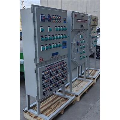
If you’ve ever stood in the back of a manufacturing plant or a commercial building’s utility room, staring at a power distribution cabinet humming softly behind steel doors, you might not think much about the tiny components tucked away inside. But for us—we’ve been power distribution cabinet suppliers for over a decade, and those components, specifically the power factor correction (PFC) systems, are the backbone of keeping that space running smoothly. I still remember a call we got three years ago from a local textile plant owner who’d been dealing with sky-high utility bills for months, convinced it was a meter error. Turns out, their old distribution cabinet lacked a properly sized PFC system, and they were being charged a penalty for lagging power factor. That story stuck with me because it drove home a simple truth: PFC isn’t just a “nice-to-have” for distribution cabinets—it’s a non-negotiable requirement for businesses that want to avoid wasting money and keep their electrical systems safe. Today, I want to break down exactly what goes into effective power factor correction for a power distribution cabinet, from our perspective as someone who designs, builds, and installs these cabinets every single week. Power Distribution Cabinet
First, let’s get on the same page about what power factor (PF) even is, because it’s easy to mix up with other electrical terms. Power factor is the ratio of real power (the actual work-doing power, measured in kilowatts or kW) to apparent power (the total power flowing through the system, measured in kilovolt-amperes or kVA). A perfect PF is 1.0, which means every bit of power is being used to run equipment. Most industrial and commercial systems have a lagging PF—usually between 0.7 and 0.9—because inductive loads like motors, transformers, and HVAC systems draw reactive power, which doesn’t do work but does create strain on the system. That strain leads to higher line losses, overheating wires and transformers, and those dreaded utility penalties. So the goal of PFC is to offset that reactive power with capacitive components, pushing PF as close to 0.95 to 0.98 as possible (that’s the sweet spot, because going too high can lead to leading PF, which has its own set of issues).
But here’s the thing: not all PFC systems are created equal, and they have to be tailored to the specific distribution cabinet and the loads it serves. The first core requirement we prioritize when designing a distribution cabinet with PFC is accurate load profiling. You can’t size a PFC system by guesswork—if you put too little in, you still get penalties; too much, and you risk leading PF and resonance. For example, a bakery we work with recently installed new commercial ovens, which are heavy inductive loads, and their old PFC system was sized for the old, smaller equipment. We had to pull 30 days of load data from their existing meters to map out peak, off-peak, and even seasonal load fluctuations—bakeries run 24/7 during holiday seasons, so their load is way higher in November and December than in July. That profiling tells us the exact reactive power needs of the system, so we can select the right capacitor bank for the distribution cabinet. We also use a power quality analyzer during the initial site survey, because it doesn’t just measure average load—it picks up on harmonic distortion, which is a huge factor I see many suppliers miss. Harmonics, those extra frequency waves from non-linear loads like variable frequency drives (VFDs) and LED lighting, can cause capacitors to overheat and fail prematurely. So any PFC system has to be designed with harmonic mitigation in mind, whether that means using tuned reactors to prevent resonance or choosing harmonic-rated capacitors that can handle distorted current.
Next, the PFC components themselves have to be compatible with the distribution cabinet’s specifications. I’ve seen too many cheaply built cabinets where someone just bolts a random capacitor bank to the side, and it causes more problems than it solves. The capacitors need to be rated for the cabinet’s operating voltage, frequency, and temperature range—most industrial cabinets operate at 480V, but some commercial ones use 208V, and using a 480V capacitor in a 208V cabinet won’t do anything, while a 208V capacitor in a 480V cabinet will blow almost instantly. We also specify self-healing capacitors for almost all our cabinets—these have a dielectric that repairs small punctures, so they last longer than old-style capacitors that fail after a few years. The contactors that switch the capacitor banks in and out are another key component. They have to be rated for high inrush current, because when capacitors turn on, they draw a short burst of extra current. Cheaper contactors can’t handle that, so they wear out fast, leading to inconsistent PFC. For larger distribution cabinets with variable loads, we use automatic power factor controllers, not manual switching. These controllers monitor PF in real time, switching capacitor steps on or off as loads change, so PF stays consistent even when a plant starts or stops production shifts. A manual system only adjusts when someone remembers to flip a switch, which means you’ll get periods of low PF and penalties.
Another non-negotiable requirement for PFC in a distribution cabinet is safety and compliance with electrical codes. We follow every NEC (National Electrical Code) and IEC (International Electrotechnical Commission) standard for our cabinets, because cutting corners here isn’t worth the risk. Capacitor banks need overcurrent protection, so we add fuses or circuit breakers specifically sized for the PFC components—without that, a capacitor short circuit can cause a fire or damage the entire distribution system. We also include discharge resistors, which bleed off the stored power in the capacitors when the system is turned off. If someone opens the cabinet to do maintenance and touches a capacitor that hasn’t discharged, that’s a fatal shock. I learned this lesson early in my career when a trainee at a previous company got a minor shock from an undischarged capacitor—we’ve never skipped discharge resistors in any cabinet we build since. Also, the location of the PFC components inside the cabinet matters. They need to be placed in a well-ventilated area, separate from heat-generating components like transformers, because high temperatures reduce capacitor lifespan. We usually mount capacitor banks on the side of the cabinet with dedicated ventilation holes, or in a separate compartment, to keep them cool.
Dynamic response is another critical requirement, especially for facilities with rapidly changing loads. Take a data center, for example—their servers turn on and off all the time, so their load shifts in seconds. A static PFC system with fixed capacitor steps can’t adjust fast enough, leading to fluctuating PF. For these applications, we use thyristor-switched capacitor (TSC) systems instead of contactor-switched ones. TSCs switch capacitors electronically, in milliseconds, so they can keep up with fast load changes, maintaining a steady PF. We recently retrofitted a data center’s distribution cabinet that had a contactor-based PFC system, and within three months, their utility bills dropped by 12%, and their PF stayed at a consistent 0.97, well above their local utility’s required threshold. That’s the kind of result that makes all the careful design work worth it.
We also consider future expandability when integrating PFC into distribution cabinets. A lot of businesses will add new equipment or expand their operations in a few years, so building a PFC system that can be easily upgraded saves them money down the line. For example, when we build a cabinet for a small manufacturing plant that plans to add a new assembly line in three years, we leave extra space in the cabinet for additional capacitor steps and make the controller compatible with adding more modules later. That way, they don’t have to replace the entire PFC system when they expand—they just add a few components, which is far more cost-effective. We also include monitoring features, so clients can track their PF, reactive power, and PFC performance remotely. Many of our distribution cabinets are equipped with IoT sensors that send real-time data to a dashboard, so clients can see if their PFC system is working, catch issues before they cause downtime, and verify that they’re not being overcharged by their utility.
I can’t stress enough how site-specific PFC requirements are. What works for a small retail store’s distribution cabinet is completely different from what’s needed for a large industrial plant or a hospital. A hospital, for example, has critical loads that can’t fail, so their PFC system needs to have redundant components and be designed with 100% reliability in mind. We recently built a custom distribution cabinet for a hospital that had two separate PFC systems, one primary and one backup, so if one goes down, the other takes over instantly, keeping PF consistent even during maintenance. On the other end, a small office building’s cabinet might use a simple automatic controller with two capacitor steps, enough to cover their moderate load of computers, HVAC, and lighting.
Let’s circle back to that textile plant I mentioned earlier. When we visited them, their distribution cabinet had a manual PFC system with only one capacitor bank. The plant had added three new large motors a year prior, so their load had increased, and the single capacitor was too small, pushing their PF to 0.72, which was below their utility’s 0.9 minimum. We designed a custom PFC system for their existing cabinet: we pulled load data for a week to map their peak and off-peak loads, added two additional capacitor steps with harmonic-rated components, installed an automatic controller, and upgraded their overcurrent protection for the capacitors. Six months later, they called us ecstatic—their monthly utility bill dropped by $1,800, and they no longer had penalty charges. That’s the impact of getting PFC right in a distribution cabinet.

If you’re a facility manager, operations director, or anyone responsible for electrical systems, the last thing you want is to be blindsided by unexpected utility penalties, equipment overheating, or unplanned downtime. Power factor correction isn’t a one-size-fits-all add-on—it requires careful load profiling, component compatibility, safety compliance, dynamic response, and future planning. As a power distribution cabinet supplier, we don’t just sell cabinets—we design them to solve specific problems, and PFC is one of the most important parts of that. If you’re struggling with high energy bills, inconsistent power quality, or outdated distribution cabinets that can’t keep up with your loads, we’d love to walk through your needs and help you find the right PFC solution for your system.
Control Cabinet References
- "Power Factor Correction for Industrial Applications," National Electrical Manufacturers Association (NEMA), 2021.
- IEC 60831, "Shunt Power Capacitors for AC Systems Rated from 0.66 kV (1 kV) up to and Including 30 kV," International Electrotechnical Commission, 2020.
- "Power Quality Harmonics and Power Factor Correction," Institute of Electrical and Electronics Engineers (IEEE) Recommended Practice, 2019.
- "Load Profiling Methods for Power Factor Correction System Sizing," International Council on Large Electric Systems (CIGRE) Report, 2022.
- "Electrical Safety Requirements for Capacitor Banks in Distribution Systems," Occupational Safety and Health Administration (OSHA), 2020.
Guangdong Baihao Electric Co., Ltd.
As one of the most professional power distribution cabinet manufacturers and suppliers in China, we also support customized service. Please feel free to wholesale discount power distribution cabinet in stock here from our factory. Quality products and low price are available.
Address: 201, 2nd Floor, Building 3, No.1, Honggang Section, Lihe Road, Lishui Town, Nanhai District, Foshan City
E-mail: jiang_baisi@126.com
WebSite: https://www.gd-baihao888.com/
